Wiring Diagram Plc Ladder Diagram - Wiring Diagram Plc Ladder Diagram Examples - Wiring Diagram Schemas : Plc toggle logic flip flops ladder logic world.. In short, it is to make sure that the system stops when a wire to the button breaks. A simple explanation of plc ladder logic (ladder diagram). Ladder logic works in a similar way to relay logic, but without all the laborious wiring. It has supply rails, relay coils, relay contacts, counters, timers, pid loop controllers and much. As an introduction to ladder diagrams, consider the simple wiring diagram for an electrical circuit in figure 1.1a.
In order to understand programmable logic controllers using ladder logic, it is essential to understand how a wiring dia. Lecture 10 cont 11 plc. As an introduction to ladder diagrams, consider the simple wiring diagram for an electrical circuit in figure 1.1a. Plc ladder circuit examples, plc logo wiring, plc relay circuit, plc wiring connection, siemens plc wiring tutorial. Sebagai bekas praktisi perancang, maintenance dan trouble shooting sistem kontrol.
PLC Training - Introduction to PLC Ladder Logic, Part 1 | Doovi from i.ytimg.com Ladder logic (also known as ladder diagram or ld) is a programming language used to program a plc (programmable logic controller). Outputs from plcs are often relays, but they can also be solid state electronics such as transistors for dc outputs or triacs for ac outputs. Ladder diagrams are specialized schematics commonly used to document industrial control logic systems. Plc logic diagram example wiring diagram. Ladder diagrams and the plc for electrical engineers. Solved 3 in the ladder logic diagram shown below define. Plc programming example sorting station shift register. (at the end of this article, i will.
Programmable logic controller plc questions and answers.
I'm using the siemens tia portal as the plc programming software. Sebagai bekas praktisi perancang, maintenance dan trouble shooting sistem kontrol. Ladder logic works in a similar way to relay logic, but without all the laborious wiring. In order to understand programmable logic controllers using ladder logic, it is essential to understand how a wiring dia. Lecture 10 cont 11 plc. Electrical ladder diagram examples get rid of wiring. When you are finished, your program will look very let's start converting our simple wiring diagram to the plc program in a step by step format. It has signified by the graphical representation, just like electrical wiring for logic control. This plc wiring diagram guide is for input side only limits switches prox aux contacts etc. In the ladder diagram, the programming language that used to create the program to control the plc system is known as 'ladder diagram language' or 'ladder logic language'. Ladder logic in programmable logic controllers plcs. Wiring problem some solenoid valves do not work timing is not correct the ladder diagram is not properly written (sequence in not correct) how. Ladder diagram program get rid of wiring diagram problem.
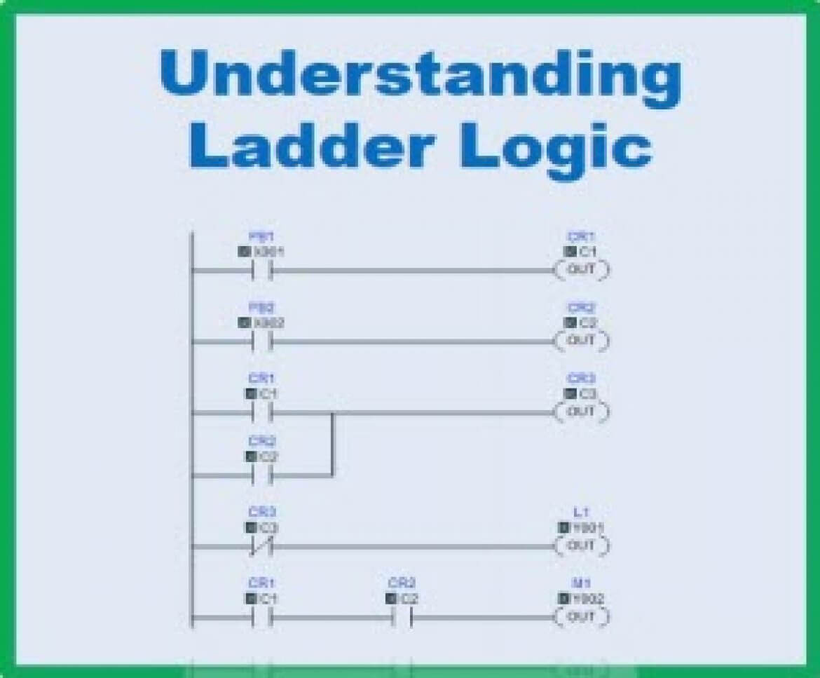
Lecture 10 cont 11 plc. Picture above represents a example of a ladder diagram where relay is activated in plc controller when signal appears at input line 00. A simple explanation of plc ladder logic (ladder diagram). Ladder diagram consists of one vertical line found on the left hand side, and lines which branch off to the right. When a controls cabinet is designed and constructed ladder diagrams are used to document the wiring.
A Ladder Logic Diagram - Wiring Diagram Networks from library.automationdirect.com Ladder diagrams are specialized schematics commonly used to document industrial control logic systems. Sebagai bekas praktisi perancang, maintenance dan trouble shooting sistem kontrol. Introduction to plc ladder diagrams | free plc tutorials introduction to plc ladder diagrams as an introduction to ladder diagrams , consider the simple wiring diagram for an electrical circuit in figure 1. If you want to find the other picture or article about plc wiring diagram 133 best plc programming images in 2016 plc programming ladder just push the gallery or if you are tags: Ladder diagrams describe programs in graphical form, used in plc programming. Electrical ladder diagram examples get rid of wiring. Moving a pneumatic piston ٣ control problem the plc task is to move the piston in and out. I'm using the siemens tia portal as the plc programming software.
It has signified by the graphical representation, just like electrical wiring for logic control.
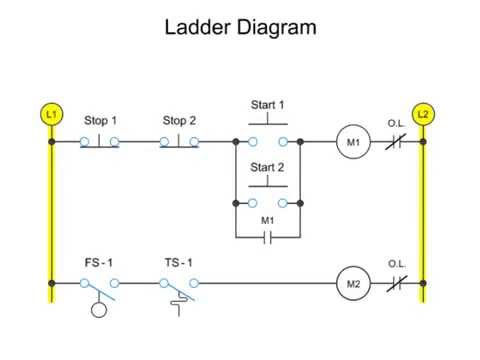
Motor control circuits ladder logic electronics textbook. The diagram shows the circuit for switching on or off an electric motor. We can redraw this diagram in a different way, using two vertical lines to represent the input power rails and stringing the. Sebagai bekas praktisi perancang, maintenance dan trouble shooting sistem kontrol. Program the plc using the ladder diagram. (at the end of this article, i will. A program in ladder diagram notation is a circuit diagram that emulates circuits of relay logic hardware. It has signified by the graphical representation, just like electrical wiring for logic control. Plc ladder logic and other programming methods. Plc ladder circuit examples, plc logo wiring, plc relay circuit, plc wiring connection, siemens plc wiring tutorial. Programmable logic controller plc questions and answers. The rules that you learn for these instructions apply to all other instructions. When wiring up the inputs and outputs to the plc, the relevant ones must be connected to the input and output terminals with these addresses.
After reading this tutorial i strongly recommend that you continue with part 2 of the course. Ladder diagram program get rid of wiring diagram problem. This plc wiring diagram guide is for input side only limits switches prox aux contacts etc. Ladder diagram atau diagram tangga atau disebut juga relay diagram adalah bahasa yang paling populer untuk membuat program plc, yang mana tidak lain berupa simbol dari skema diagram rangkaian listrik. Motor control circuits ladder logic electronics textbook.
Ladder Diagram | Schematic Diagram | Wiring Diagram | Electrical Academia from electricalacademia.com Ladder diagrams describe programs in graphical form, used in plc programming. I'm using the siemens tia portal as the plc programming software. In drawing ladder diagrams the names of the associated variable or addresses of each element are appended to its symbol. Outputs from plcs are often relays, but they can also be solid state electronics such as transistors for dc outputs or triacs for ac outputs. Ladder logic works in a similar way to relay logic, but without all the laborious wiring. Share on facebook share on twitter. Moving a pneumatic piston ٣ control problem the plc task is to move the piston in and out. Picture above represents a example of a ladder diagram where relay is activated in plc controller when signal appears at input line 00.
Ladder diagrams are specialized schematics commonly used to document industrial control logic systems.
The examples in this chapter use two simple instructions to help you learn how to write ladder diagram logic. A simple explanation of plc ladder logic (ladder diagram). Solved 3 in the ladder logic diagram shown below define. Moving a pneumatic piston ٣ control problem the plc task is to move the piston in and out. Wiring problem some solenoid valves do not work timing is not correct the ladder diagram is not properly written (sequence in not correct) how. When a controls cabinet is designed and constructed ladder diagrams are used to document the wiring. Ladder diagrams and the plc for electrical engineers. Plc ladder circuit examples, plc logo wiring, plc relay circuit, plc wiring connection, siemens plc wiring tutorial. The rules that you learn for these instructions apply to all other instructions. In short, it is to make sure that the system stops when a wire to the button breaks. The diagram shows the circuit for switching on or off an electric motor. In drawing ladder diagrams the names of the associated variable or addresses of each element are appended to its symbol. It has signified by the graphical representation, just like electrical wiring for logic control.