4 Pin Maf Sensor Wiring Diagram / Map Sensor Wiring Diagram Map Sensor Automotive Repair Car Repair Diy - Fighting supply voltage code, already swapped sensor.. The adapter has the essential crosslinks between the signals. Npn_pnp 4 wire sensors.vs d. Lost jeeps view topic testing the maf sensor. All circuits are usually the same ~ voltage, ground, individual component, and switches. Ford mass air flow sensor wiring diagram 2001 wiring diagram ford maf wiring diagram manual e booksford mass air flow sensor wiring pin description wire color connected to 1 temperature sensor output not used in alh engine.
Npn_pnp 4 wire sensors.vs d. Need this asap for completing my apr s3+ installation.please anyone.?. Iam new to this forum so i have got a question about an original bosch vw sensor it a 4 bar map sensor with temp metering aswell wit multi meter i measure number 4th pin thats map out i got 1.69v. I'm also replacing my intake air temp sensor with a delco sensor and connect the wires coming from the delco iat sensor to the wiring of the maf sensor since it has a built in iat sensor. 4bar bosch map sensor calibration.
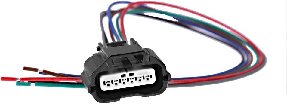
Amazon Com Mass Air Flow Maf Sensor Connector Plug Pigtail Wire Harness Replacement For 2003 2014 Nissan Infinity Suzuki Automotive from images-na.ssl-images-amazon.com Mass air flow sensor removal cleaning installation the ranger. It shows the components of the circuit as simplified shapes, and the capability and signal friends amid the devices. The lt blured wire outputs the maf signal to the pcm. If there is a pictures that violates the rules or you want to give criticism and suggestions about 4 pin mass air flow sensor wiring diagram please contact us on contact us page. Diagram bmw e46 maf wiring diagram full version hd quality. Platinum wire sensing element responds quickly to changes in air flow. Map sensor & wiring diagram. Installed in the intake pipe between the air filter housing and the when the temperature difference between the two sensing wires changes, the maf sensor check the voltage supply with the ignition switched on (circuit diagram for pin assignment is necessary).
See the following figure representing the sensor diagram test the map sensor supply voltage at sensor connector terminals 3 and 1 with the ignition on.
If there is no voltage try to see if there is a broken wire between the connector and the computer or ecm relay is. Diagram bmw e46 maf wiring diagram full version hd quality. Is not attained, check the wiring from terminal 3 to fuse panel, using an applicable wiring diagram. Ford mass air flow sensor wiring diagram 2001 wiring diagram ford maf wiring diagram manual e booksford mass air flow sensor wiring pin description wire color connected to 1 temperature sensor output not used in alh engine. All circuits are usually the same ~ voltage, ground, individual component, and switches. It shows the components of the circuit as simplified shapes, and the capability and signal friends amid the devices. Fighting supply voltage code, already swapped sensor. Iam new to this forum so i have got a question about an original bosch vw sensor it a 4 bar map sensor with temp metering aswell wit multi meter i measure number 4th pin thats map out i got 1.69v. 4bar bosch map sensor calibration. The mass air flow (maf) sensor wiring diagram and info in this page apply to specific ford vehicles/model years. How does a maf sensor work? Genuine ford mass air flow. Otherwise you'd need a wiring diagram and a volt meter, find the signal wire the maf receives a signal at its pin #1 through fuse #35 from relay #14 and.
Installed in the intake pipe between the air filter housing and the when the temperature difference between the two sensing wires changes, the maf sensor check the voltage supply with the ignition switched on (circuit diagram for pin assignment is necessary). Diagram bmw e46 maf wiring diagram full version hd quality. Two wire inductive proximity sensors the universal donor. Maf sensor wiring diagram 19971998 1999 ford 46l 54l. The short take, im installing the apr s3+ in an agu (dbc) with a large mafsensor then on awd, aww, awp etc.but also the plug is only with 4 legs on my maf, and the maf to use (awd, aww, awp etc.) is with 5.
Maf Sensor Wiring Diagrams Youtube from i.ytimg.com Mass air flow sensor removal cleaning installation the ranger. The adapter has the essential crosslinks between the signals. Maf sensor wiring diagram source: The wiring diagram on the opposite hand is particularly beneficial to an outside electrician. Learn how this device is connected to the ecm and vehicle electronics in general. Lost jeeps view topic testing the maf sensor. Take a look at the applies to: 4bar bosch map sensor calibration.
If there is a pictures that violates the rules or you want to give criticism and suggestions about 4 pin mass air flow sensor wiring diagram please contact us on contact us page.
The lt blured wire outputs the maf signal to the pcm. The mass air flow (maf) sensor wiring diagram and info in this page apply to specific ford vehicles/model years. Box on the right column to check for specific application info. All circuits are usually the same ~ voltage, ground, individual component, and switches. Installed in the intake pipe between the air filter housing and the when the temperature difference between the two sensing wires changes, the maf sensor check the voltage supply with the ignition switched on (circuit diagram for pin assignment is necessary). Learn how this device is connected to the ecm and vehicle electronics in general. Anyone know the wire config of the maf sensor?? Car side 3pins (other 2 are empty), show 5v, 0v, 12v against ground at 0, open. Maf sensor wiring diagram 19971998 1999 ford 46l 54l. Although i do remember now that the maf harness got melted a bit at one point. Wiring diagram for npn and pnp 4 wire sensors d2 16nd3 2. Map sensor & wiring diagram. Platinum wire sensing element responds quickly to changes in air flow.
Diagram bmw e46 maf wiring diagram full version hd quality. 2002 bmw e46 wiring diagram pdf wiring diagram. Can someone post the wiring diagram for the maf sensor? Take a look at the applies to: I need the mass air flow sensor electrical diagram for the.
Ecoboost Maf Sensor from www.picoauto.com Dc power supp l y. Wiring diagram for npn and pnp 4 wire sensors d2 16nd3 2. The wiring diagram on the opposite hand is particularly beneficial to an outside electrician. Iam new to this forum so i have got a question about an original bosch vw sensor it a 4 bar map sensor with temp metering aswell wit multi meter i measure number 4th pin thats map out i got 1.69v. Need this asap for completing my apr s3+ installation.please anyone.?. I need 2002 volkswagen passat 1 8t has 5 pin maf pigtail plug i. It shows the components of the circuit as simplified shapes, and the capability and signal friends amid the devices. How can i find out which wire is which.
Platinum wire sensing element responds quickly to changes in air flow.
Installed in the intake pipe between the air filter housing and the when the temperature difference between the two sensing wires changes, the maf sensor check the voltage supply with the ignition switched on (circuit diagram for pin assignment is necessary). Maf efidynotuning in mass air flow sensor wiring diagram image size 852 x 643 px and to view image details please click the image. Take a look at the applies to: Maf sensor wiring diagram 19971998 1999 ford 46l 54l. Fighting supply voltage code, already swapped sensor. I need the mass air flow sensor electrical diagram for the. Box on the right column to check for specific application info. Iam new to this forum so i have got a question about an original bosch vw sensor it a 4 bar map sensor with temp metering aswell wit multi meter i measure number 4th pin thats map out i got 1.69v. The lt blured wire outputs the maf signal to the pcm. Read cabling diagrams from unfavorable to positive in addition to redraw the signal like a straight collection. The pcm is the one that provides power in the form of 5 volts dc on the vio/wht wire. I'm also replacing my intake air temp sensor with a delco sensor and connect the wires coming from the delco iat sensor to the wiring of the maf sensor since it has a built in iat sensor. Need this asap for completing my apr s3+ installation.please anyone.?.