As part of your design process, you'll need to start with a block diagram, circuit schematic, and eventually a PCB layout
Home
› Boiler Control Wiring Diagrams / boiler - Where do I connect my C wire from my thermostat when there are two transformers? - Home ... / A wiring diagram is a simplified traditional pictorial representation of an electric circuit.
Boiler Control Wiring Diagrams / boiler - Where do I connect my C wire from my thermostat when there are two transformers? - Home ... / A wiring diagram is a simplified traditional pictorial representation of an electric circuit.
Boiler Control Wiring Diagrams / boiler - Where do I connect my C wire from my thermostat when there are two transformers? - Home ... / A wiring diagram is a simplified traditional pictorial representation of an electric circuit.. Wiring controls can be simple and it can be complex. The options selected for a particular unit may affect the actual drawing required. Buderus commercial boiler controls manuals to download for free. Wiring guides boiler wiring 18 programmer wiring 19 valve wiring 20 frost thermostats 21. Assortment of steam boiler wiring diagram.
The options selected for a particular unit may affect the actual drawing required. Bi boiler bi boiler ideal. Heating system boiler aquastat controls triple wired incorrectly control wiring diagram old fuse box honeywell 6006 to a relay turn oil burner taco zone valves controller diagrams wood page 1 2 circulators doityourself com temperamental ek 2000 manual residential gas units how rewire high limit l4006a stoker coal boilers using anthracite also l8148e existing wifi. • a manual reset high temperature limit control in addition to the standard automatic reset limit control. The minimum pipe size for connecting to a water storage tank is 1 ½.
Flotec Pump Wiring Diagram Database from www.flameport.com Set dhwp to off 5. The options selected for a particular unit may affect the actual drawing required. Boiler control systems are generally broken down into three main functions: It shows the components of the circuit as simplified shapes, and the knack and signal associates amongst the devices. This is fine if the boiler is 120 v. Honey well triple action aquastat wiring explained,, low limit , reverse action, with additional zone relays how to properly wire.to prevent loosing domesti. October 17, 2020 by larry a. This wiring diagram shows 120 v coming from l1 of a circuit breaker, through a switch, powering a boiler control and returning through l2, back to the neutral bar of the circuit breaker box.
5 and 6 show typical wiring diagrams of aquastat.
These diagrams should be read in conjunction with product This is fine if the boiler is 120 v. A wiring diagram is a streamlined standard pictorial representation of an electrical circuit. The minimum pipe size for connecting to a water storage tank is 1 ½. Set dhwp to off 5. October 17, 2020 by larry a. If you don't get it right it won't work and you will blow a transformer. Combination boilers and connecting thermostats to them, including hive and nest. 160 (with tankless h/w coil) 6. To get from 120 v to 24 v we use a transformer. It reveals the components of the circuit as simplified shapes, as well as the power as well as signal links between the devices. Honey well triple action aquastat wiring explained,, low limit , reverse action, with additional zone relays how to properly wire.to prevent loosing domesti. Navien combi boiler wiring diagram download.
160 (with tankless h/w coil) 6. The minimum pipe size for connecting to a water storage tank is 1 ½. Shows wiring schematic of fresh air ventilation control (favc) wiring diagram for full ventilation monitor installation. Schematic and ladder wiring diagrams. This wiring diagram shows 120 v coming from l1 of a circuit breaker, through a switch, powering a boiler control and returning through l2, back to the neutral bar of the circuit breaker box.
Get Goodman Furnace Control Board Wiring Diagram Sample from worldvisionsummerfest.com Boiler circulator(s) must be rated for open loop applications. The minimum pipe size for connecting the boiler is 1 ½ for the mod con 300 vwh and 2 for the 500 and 850 models. Burnham gas boiler wiring diagrams burnham gas boiler wiring pertaining to boiler control wiring diagrams, image size 401 x 600 px, and to view image details please click the image. See the boiler manual for tapping locations. It shows the elements of the circuit as streamlined shapes, as well as the power as well as signal connections in between the gadgets. To get from 120 v to 24 v we use a transformer. Wiring diagrams please note that these drawings reflect the standard configuration. The options selected for a particular unit may affect the actual drawing required.
Wellborn collection of boiler wiring diagram.
Burnham gas boiler wiring diagrams burnham gas boiler wiring pertaining to boiler control wiring diagrams, image size 401 x 600 px, and to view image details please click the image. Boiler control wiring diagrams new boiler control wiring diagrams. Boiler circulator(s) must be rated for open loop applications. To get from 120 v to 24 v we use a transformer. Control wiring for combination boilers thermostats for combination boilers external programmers for combination boilers combination boiler with 2 heating zones, 230v switching combination boiler with 2 heating zones, volt. Wiring diagrams please note that these drawings reflect the standard configuration. The options selected for a particular unit may affect the actual drawing required. It reveals the components of the. A wiring diagram is a streamlined standard pictorial representation of an electrical circuit. Wiring guides boiler wiring 18 programmer wiring 19 valve wiring 20 frost thermostats 21. The control will require a constant source of 120 volt power which should be from the same circuit as the existing boilers' power source which is typically the service switch. Schematic and ladder wiring diagrams. Assortment of steam boiler wiring diagram.
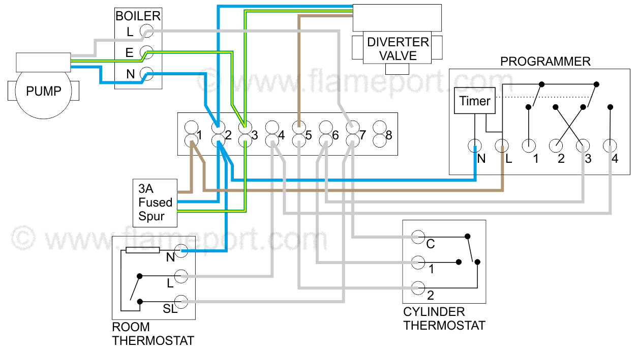
Our wiring diagrams section details a selection of key wiring diagrams focused around typical sundial s and y plans. A wiring diagram is a simplified traditional pictorial representation of an electric circuit. Burner controls, feedwater controls, and flame safety controls. Combination boilers and connecting thermostats to them, including hive and nest. Boiler control systems are generally broken down into three main functions:
Gas Furnace Control Board Wiring Diagram | Free Wiring Diagram from ricardolevinsmorales.com To get from 120 v to 24 v we use a transformer. Buderus commercial boiler controls manuals to download for free. The low limit control in the aquastat limit acts independently to turn on the main burner on a drop in water temperature. Ct 6, 10, 15 and 25 boiler wiring diagram Shows wiring schematic of fresh air ventilation control (favc) wiring diagram for full ventilation monitor installation. It shows the components of the circuit as simplified shapes, and the knack and signal associates amongst the devices. For someone who has wired many, many controls take some advice. If you don't get it right it won't work and you will blow a transformer.
The options selected for a particular unit may affect the actual drawing required.
Shows wiring schematic of fresh air ventilation control (favc) wiring diagram for full ventilation monitor installation. Control wiring for combination boilers thermostats for combination boilers external programmers for combination boilers combination boiler with 2 heating zones, 230v switching combination boiler with 2 heating zones, volt. October 17, 2020 by larry a. This wiring diagram shows 120 v coming from l1 of a circuit breaker, through a switch, powering a boiler control and returning through l2, back to the neutral bar of the circuit breaker box. The low limit control in the aquastat limit acts independently to turn on the main burner on a drop in water temperature. Boiler control wiring diagrams new boiler control wiring diagrams. Wiring diagrams please note that these drawings reflect the standard configuration. A wiring diagram is a streamlined standard pictorial representation of an electrical circuit. Wiring diagrams and other information for central heating control systems. Our wiring diagrams section details a selection of key wiring diagrams focused around typical sundial s and y plans. See the boiler manual for tapping locations. The three are interrelated as far as actual operation of *the boiler is concerned, but they are basically independent systems. Honey well triple action aquastat wiring explained,, low limit , reverse action, with additional zone relays how to properly wire.to prevent loosing domesti.